Beam structure
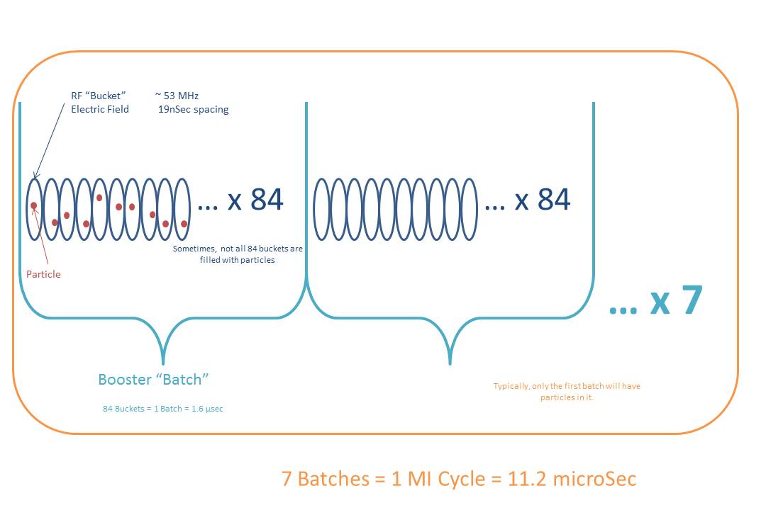
19 nanoseconds = 1 RF bucket (53 MHz)
1.6 microseconds = size of booster (84 RF buckets), called a “batch”
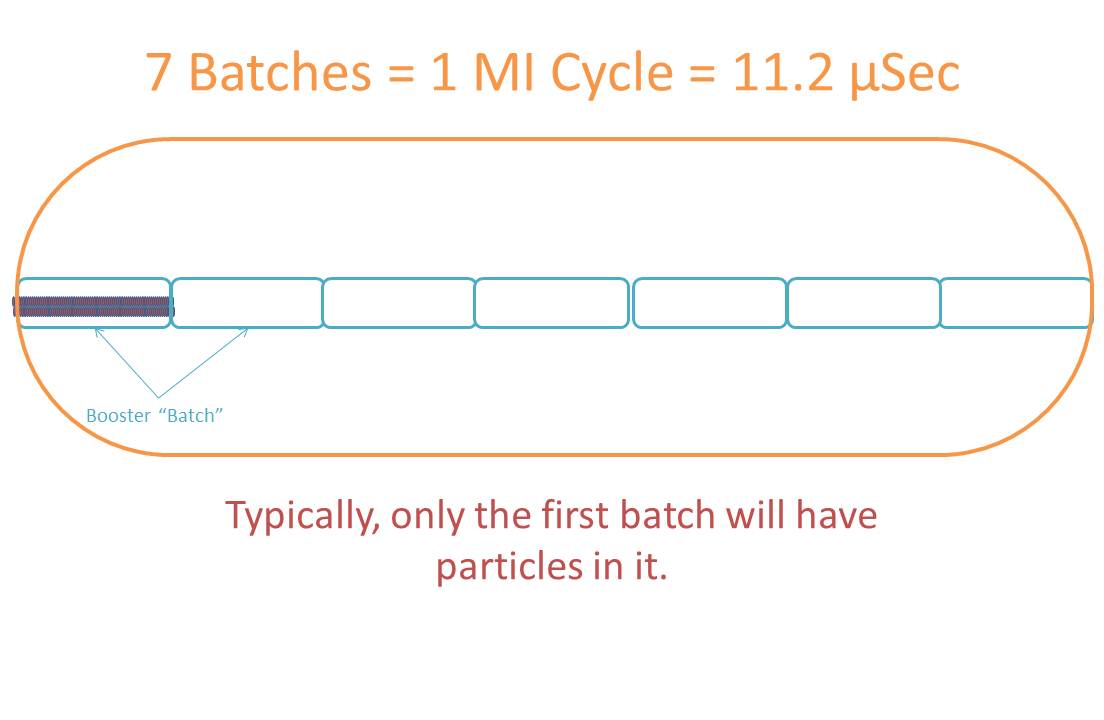
11.2 microseconds = size of Main Injector (7 Batches)
4.2 seconds = length of spill
60 seconds = approximate rep rate of spill
Creating the beam
 750keV H-minus ions are extracted from the source into the Linac. The Linac accelerates the ions to 400MeV, and then extracts them to the Booster Accelerator. As the ions are injected into the Booster, the electrons are stripped off leaving 400MeV protons to circulate in the Booster.
The Booster captures the protons into 84 bunches (1 batch) and accelerates them to 8GeV. Each of these bunches is 19 nsec long. Typically, 8 – 30 of these bunches are extracted to the Main Injector for Test Beam operation (a process known as partial-batching.) At the injection total energy of E = 8:938 GeV, the Main Injector has a circumference in time of T0 = 11:13 µs, which is exactly 7 booster batches long.
The Main Injector accelerates the beam to 120GeV at a frequency of 53 MHz, at which point a process called Resonance Extraction is started and a fraction of the beam is resonantly extracted in a slow spill for each Main Injector rotation.
Extraction from the Main Injector
 The beam is extracted from the Main Injector using the QXR quadrupole circuit to resonantly extract beam over 4.2 seconds ($21 event.) Quadrupole eXtraction Regulator (QXR) is the system that controls the rate of extraction from the Main Injector. It is composed of a microprocessor system that controls special air core quadrupoles in the Main Injector. Using this process, a portion of the beam is shaved off, into the extraction line, on every rotation the beam makes around the machine. Be aware that QXR takes time to learn when beam is first established.
If beam were extracted smoothly, only one particle per Main Injector RF bucket would be extracted per rotation, but for intensities up to 100 kHz, double occupancy occurs 35% of the time and two particles are extracted instead. This percentage can increase at higher intensities.
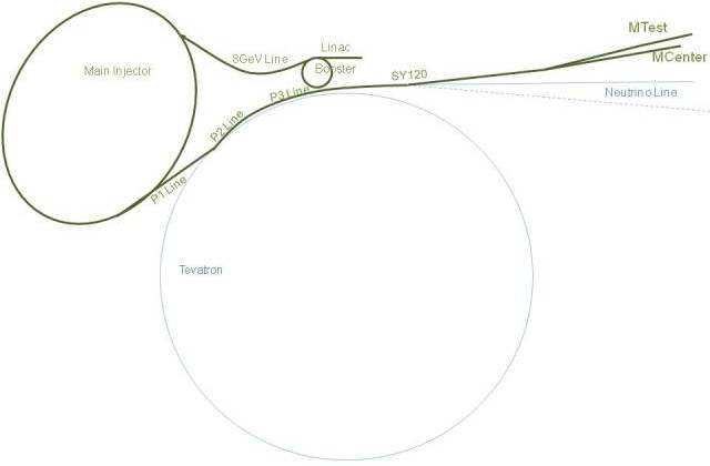
The beam can follow many different paths, but the path towards the test beam facility follows the P1 line to the P2 line to the P3 line. At the end of the P3 line, the Switchyard begins, and the beamline branches away from the Tevatron to the Enclosure B, C, D, E, etc.
Towards the end of Enclosure B, the beam is split. The position of the Meson Septa, S:MSEP, determines whether the beam will pass through the magnetic field gap to be bent west and continue onward to Meson, or the field-free region of S:MLAM onto S:V100 which will bend it into the Neutrino beamline or let it pass through to the SY dump (located in Encl C).
Next up is the F1 manhole, notable for containing the electrostatic septa (FSeps) that are capable of splitting the “Meson” beam vertically into 2 streams. Finally, the two streams of beam continue through the F2 and F3 manholes to the first Meson Area enclosure, M01. At the upstream end of M01, the 2 vertically separated streams of beam have now diverged to about 1 inch apart, and rise up at about 1 degree. The upper stream is bent horizontally west into the MTest beamline by the MW1W splitting magnet. The lower stream of protons travels through the center, field-free region of the MW1W splitting magnet, and F:MC1D, then bends the beam slightly downward into the MCenter beamline.
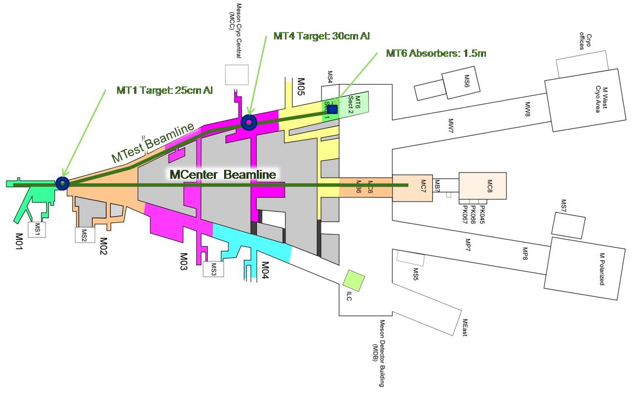
MTest and MCenter share enclosures M01, M02, M03 and M05. By the end of M05, the beam lines have diverged sufficiently so there is finally room for independent enclosures, target halls, and shielding for each beam line. MTest concludes in enclosures MT6.1 & MT6.2, while beam to MCenter continues through enclosures MC6 to MC7. MC8 and the empty MBottom enclosure MB7 do not contain any MCenter beam line elements, but due to potential muon radiation from the MC6 target station, they must be interlocked for MCenter beam operation.
MTest beamline
There are 2 movable targets in the MTest beamline:
- MT1 Target: 435 meters upstream of MT6; 25cm aluminum
- MT4 Target: 145 meters (949 ft) upstream of MT6; 30cm aluminum
There is also
- a pinhole (1mm x 1mm) collimator (MT3CH) in MT3; and
- two absorbers each 1.5 m long at the end of the MT6.2 enclosure (F:MT6AB1,2)
The MT1 target is about 700 ft upstream of MT4TGT. Secondary particles are created in the MT4 target, MT4TGT. These objects can be moved in various configurations to create the following beam modes:
- Primary Beam
- Proton Mode: 120 GeV protons – MT1 target is IN, Quads off, a pinhole collimator used to attenuate the beam and MT4TGT is out.
- Secondary Beam
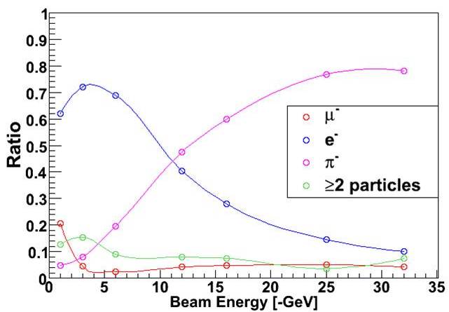
- Pion Mode: 8 – 66 GeV beam – MT1 target moved IN, Quads off, tuned for secondaries
- Low Energy Pion Mode: 1 – 32 GeV beam – MT1 target is out, Quads On, MT4 target moved in, tuned for secondaries
- Muon Mode: Any of above modes with MT6 beam absorbers closed. The best rates are given in the Low E Pion Mode at 32 GeV -at 300,000 particles per spill, you should get several thousand muons per spill, over an area of 1 square meter.
There are three sets of focusing magnets downstream of the target:
- a triplet MT4Q1, MT4Q2,MT4Q3
- a triplet MT4Q4,MT4Q5,MT4Q6
- a final doublet MT5Q1,MT5Q2
The momentum is selected by the two dipole settings:
- T4W1, MT4W2
- MT5E1-5
The beam position can be tuned by 5 trim/vernier magnets to make small corrections:
- MT4HT, MT4VT
- MT5VT1
- MT5HT2,MT5VT2
There are 4 collimators that can be used:
- MT4CH1 – a momentum selection collimator which can be closed down to reduce the momentum spread
- MT4CV1,MT4CV2,MT4CH2 are “beam scrappers”
MCenter beam
The MCenter beamline is currently used by PixLAr,NOvA, and LArIAT. The secondary beam is available, and there are 2 tertiary beam lines available.
This section will be updated with more information shortly.