Table 2B

Table 2B
Table 2B is the upstream movable die cart in section 2B. It has a capacity of 1500 pounds and a platform measuring 4ft x 3.5ft. The entire cart is driven by a worm gear attached to the floor.
Horizontal movement total is 55 inches (1397 mm) travel east, and/or west of beam center. Vertical lowest position is 38 inches (965 mm) under the beam, with 14.5 inches (368 mm) of travel.
To turn the table on just pull the emergency off button out. The position of the tables is determined absolutely, so there will be memory of their current location after power out.
If there is ever any question of safety, please crash the power button on the control box (in the enclosure).
Table 2C
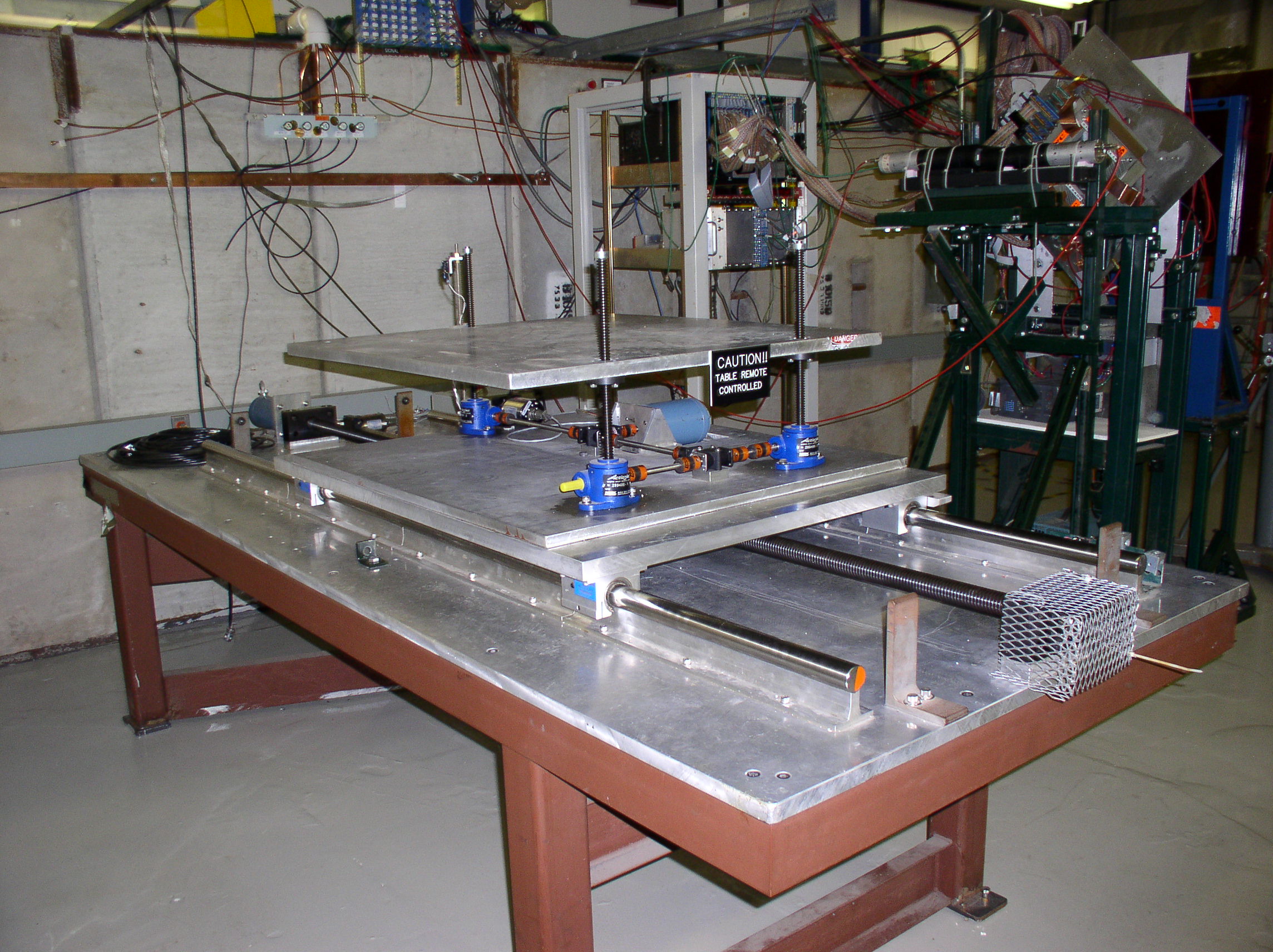
Table 2C is the downstream table in section 2 with a small platform for both horizontal and vertical motion, measuring 3sqft or 92cm x 92cm. Usable space on the table top is 36-inch x 32-inch (the lift rods restrict you to the 32″). The table has about 10 1/2 inch of travel vertical total and 42 inch horizontal movement. The lowest point of the table top is approximately 20 inches below the beam line (46 inches off floor) yet the table legs can be shimmed up a max of 6 inches. It is rated for approximately 500 lbs.
The table usually sits inside the MT6.2C hut, but it can be moved as desired. The emergency stop button is mounted on the table, but there are no manual controls inside the enclosure for this table. This table has continuous variability in speed.
Table 1A
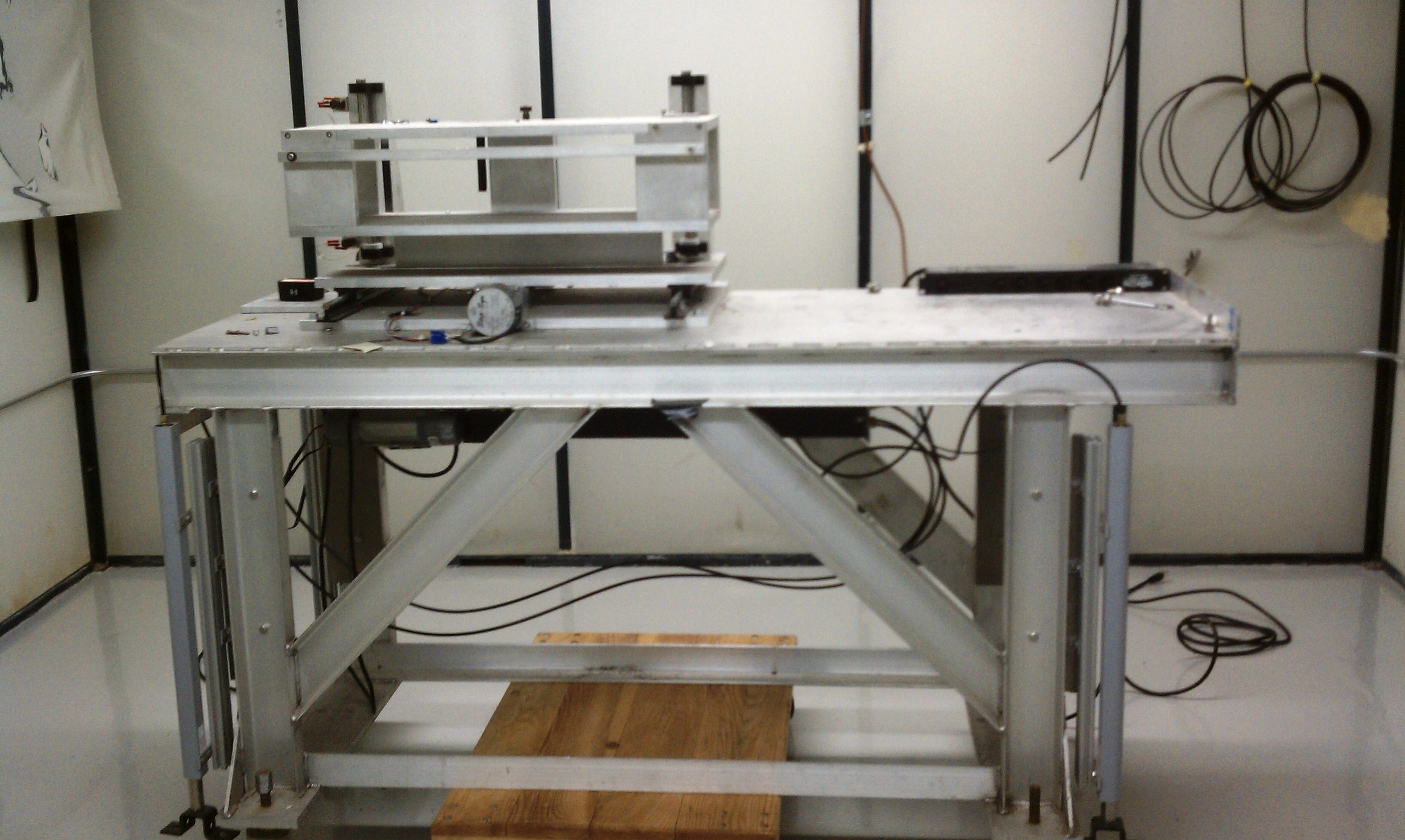
Table 1A is located in section 1 within the climate-controlled 1A hut. It consists of two tables, a larger, hydraulically controlled base for coarse vertical movement in and out of the beam, and a small, upper platform with horizontal and vertical fine control movement. The small, upper platform is 30 inches long, by 10 inches wide. The larger table underneath is 72 inches long by 25 inches wide. There are 23 inches of clearance when both tables are at their highest points, and 43 inches of clearance at their lowest.
The smaller platform can either be controlled via the rack-mounted control box in the Alcove Control Room or through a Microsoft Excel spreadsheet. The control panel for automated motion is in the rack next to the computer in the Alcove Control Room. It is important to note that if you command the table to move to a certain location through the control box, the Excel spreadsheet will not detect the movement. You would have to recalibrate the machine by sending it to “home” using Excel to get accurate positioning. If the CPU button on the control box is on, then the Excel spreadsheet will override the control box. The position of the tables are determined absolutely, so there will be memory of their current location after a power outage.
On the control box, there is an option for horizontal (X) or vertical motion (Y) for the smaller of the tables, so press the motion switch you want to control. To move the table up, flip the switch to the left. To move the table down, flip the switch to the right. If you just want to jog the table and watch the motion, then turn on the video display above the control panel to view the table you are interested in, push the jog button in the direction you want to move, and let go when you are satisfied with the position.The limit switch buttons will light up when you have reached a limit. Be aware that vertical movement (Y) is significantly slower than moving horizontally. It takes 8 seconds to move a mm horizontally and a minute to move a mm vertically.
To use the Microsoft Excel spreadsheet, you must first turn off the control box. At this point it can be aligned professionally using the hand wheels to center the detector in the beam. You can then power on the control box and turn on CPU control so that the mortars are locked. It will be your choice whether you would like to zero this alignment by putting zero into B25 (left/right) and B26 (up/down). Lets say you would like to move your detector to the left 10 cm from that alignment for some reason, you would have to click on B25 and multiply -283.67×100 to move 100 mm to the left. Let’s also assume you don’t have access to the motion table because the beam is on and you’re receiving data that doesn’t make sense. If you would like to make sure it’s not an alignment issue, you would have to “home” horizontally or vertically in either direction before the beam is actually on (it would be easier to do so horizontally), write down that number, “go to” a specific alignment in that same motion then “home” again to make sure that value is the same as before to a hundredth of a mm.
Other motion devices
| MFR | Model | Description | Qty | Displacement | load Cap. |
|---|---|---|---|---|---|
| Daedal | 5″ Slide | Linear Stage | 2 | 50.8mm | 77 Lbs. Hor. |
| Newport | MTM200PE1 | Linear Stage | 1 | 200mm | 225 Lbs Hor. |
| Newport | RTM160PE | 5″ Rotary Table | 1 | 270° | 405 Lbs. Hor. |
| Newport | Series 443 | Linear Stage | 2 | 50.8mm | 58 Lbs. Hor. |
| Slo-Syn | Type 12T | 12″ Rotary Table | 1 | 270° | Tested @ 974 Lbs. Hor. |
| Fermi | MT6.1A | X/Y Table | 1 | 125mm Vert / 125mm Hor. | Unknown at this time |
| Fermi | MT6.2B | X/Y Table | 1 | 377mm Vert / 2838mm Hor. | 1500 Lbs. / 10K Lbs |
| Fermi | MT6.2C | X/Y Table | 1 | 276mm Vert / 1111mm Hor. | Tested @ 957 Lbs. |
| Fermi | M03 | X/Y Table | 1 | 290mm Vert / 581mm Hor. | Tested @ 490 Lbs. |